Demystifying Azimuth Thrusters: maritime navigation at first
Earlier we discussed different types of thrusters in the article “Components of the DP system - Thrusters”. Dynamic Positioning (DP) systems maintains the position and heading of a vessel or offshore floating unit by means of thrusters, without the need for anchors. Thrusters play a crucial role in DP systems by providing the necessary thrust for position and heading control.
Azimuth thruster is capable of rotating 360 degrees. Being able to develop the thrust in any direction, a vessel with azimuth thrusters has good maneuvering characteristics. Azimuth thrusters can be both auxiliary and main source of thrust development, and they may have fixed-pitch propellers or controllable-pitch propellers.
The pod is typically located below the waterline and can be rotated by a hydraulic or electric motor.
By having the ability to rotate the thrust vector, ships equipped with azimuth thrusters can change direction of movement quickly and easily, making them highly maneuverable. This makes them particularly useful for tugboats, offshore supply vessels, and dynamic positioning systems for maintaining the position of floating structures.
The size and power of azimuth thrusters can vary depending on the specific application and vessel size. They are typically electrically or mechanically driven and can range from a few hundred kilowatts to several megawatts in power.
But sometimes the specific tasks require to limit sector of azimuth thruster rotation. For this purpose there are several modes available in the DP System.
Fixed Azimuth function can be usable when the thruster force is necessary to fix in a particular direction. This function shall be used when the vessel has an azimuth thruster located in the fore-and-aft centre line, usually closer to the bow from the midships and aimed to act against main environmental force, depending on which one is stronger at present moment: wind, current or their interaction. Thus, such an azimuth thruster takes the main load while the others just correct the vessel’s position with the minimum one.
While fixed, azimuth thrusters don’t provide the vessel with such a maneuverability, as a fully steerable azimuth thrusters. But they are still valuable propulsion systems in certain applications, providing additional thrust and maneuvering capabilities to enhance vessel control in specific directions.
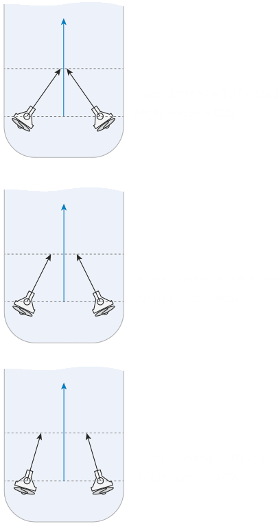
Biasing Mode is a mode, when two azimuth thrusters work compensating each other (in opposite directions), e.g. it is used in light environmental conditions to avoid constant thruster spin (hunting for a direction). Thruster Biasing has three main parameters: minimum load, at which azimuth thrusters work against each other (counteract); working sector of azimuth thrusters (Angle factor) and load percentage of the azimuth thrusters, when they exit ‘Biasing Mode’ and start working in the same direction, sharing the load demand (Turn factor). In the neutral condition, therefore, two thrusters work in the opposite direction with the power load, set by the operator. In order to provide sustained direction of forward or aft movement, both azimuth thrusters pivot within the predetermined sector, so that the sum linear vector is developed, while lateral vectors compensate each other. They can increase force making the vessel move faster, but they cannot decrease it lower than the level, set by the operator. In order to provide movement to port or starboard direction, one azimuth thruster develops more force than the other.
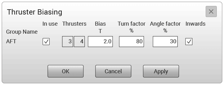
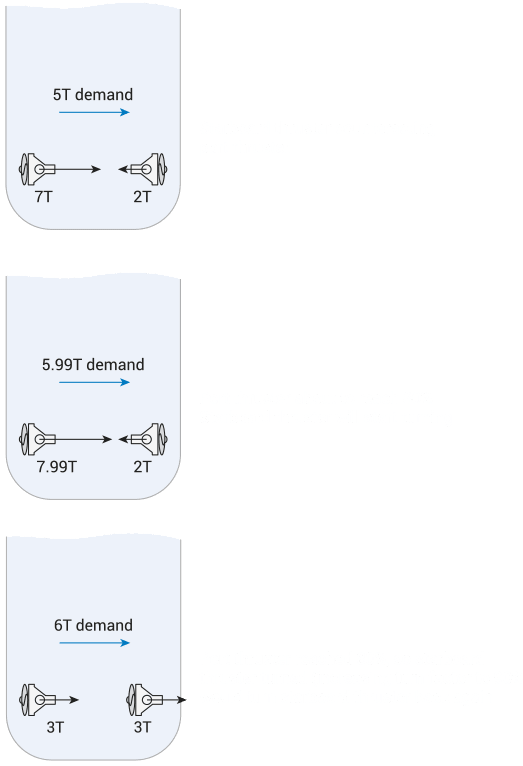
The Turn factor determines when to turn a thruster within a group, instead of continuing to counteract the other thruster. The maximum force for each thruster is 10 tones and the idle or bias force is 2 tones.
The Angle factor determines the relative priority of angle against force to satisfy the force demand. The same 10 tones demand ahead is achieved, but more thrust is used with a higher angle factor, than with a lower angle factor.