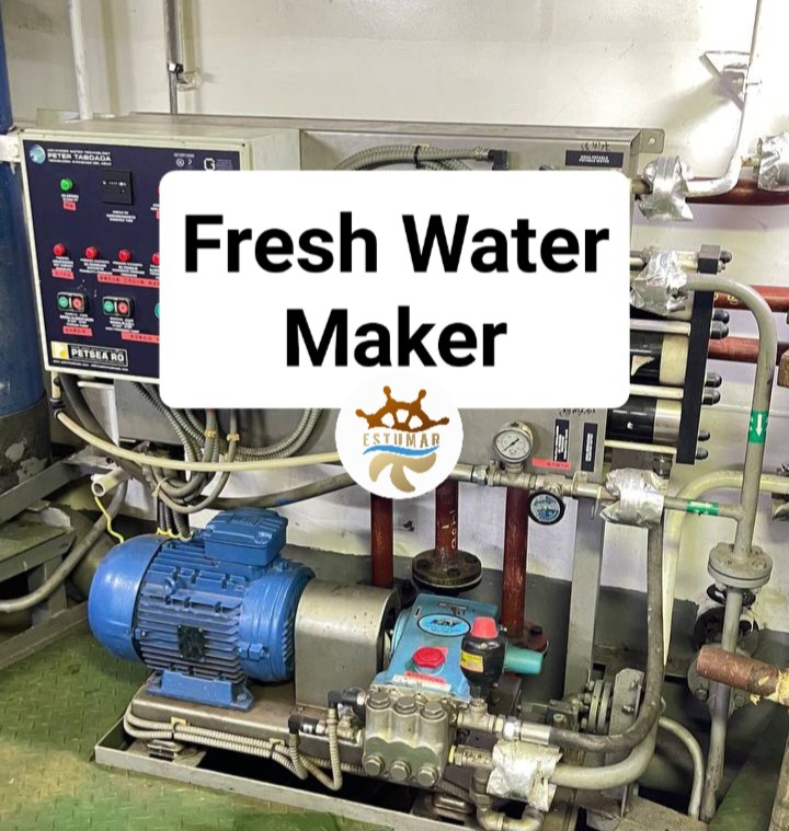
Storing large quantities of fresh water on board ship is costly and takes up valuable space. An alternative solution, in the form of a process and technology for sea water desalination - fresh water generator.

Fresh water generators (FWG) convert seawater (saltwater) to fresh water. FWGs are a common site on many marine vessels as it allows them to generate the fresh water they need whilst at sea. The process of generating fresh water is achieved via distillation.

There are three main methods employed for generating fresh water from seawater, these are boiling, evaporating and reverse osmosis (RO). Most marine vessels and industrial plants produce fresh water using either evaporators or RO plants. Large desalination plants may be connected to the steam circuit of a thermal power station, the steam is used to evaporate seawater.

A FWG consists of the following main components:
  • Hot and cold water connections
  • Shell
  • Condenser
  • Evaporator
  • Demister
  • Fresh Water Pump
  • Ejector/Eductor
  • Temperature Monitoring Devices
  • Air-Purge Valve
  • Safety Relief Valve (SRV)
  • Salinometer

Low pressure flash evaporators are connected to a seawater and hot water system. On marine vessels, seawater is sourced directly from the sea chest whilst hot water is sourced from the engine jacket water system (engine cooling water system).

The upper part of the FWG houses a condenser plate heat exchanger whilst the lower part houses an evaporator plate heat exchanger. The condenser allows seawater to pass through the heat exchanger in a closed system. The evaporator allows hot water to pass through the heat exchanger in a closed system. Both the condenser and evaporator are not fully sealed heat exchangers, the gaskets are modified to allow seawater to evaporate from the evaporator plates and fresh water to condense on the condenser plates. In short, plate heat exchangers usually have two fully closed systems, but in a FWG, one system per heat exchanger is closed and the other is open.

A demister is installed between the condenser and evaporator. The condenser, evaporator and demister are housed within the FWG shell.

Fresh water from the FWG condenser is pumped to a storage tank by a fresh water pump (usually a small centrifugal pump). An ejector/eductor is used to create and maintain a vacuum within the shell; it also removes brine (water with high salinity) from the lower part of the shell.

The temperature within the shell, seawater system and jacket water system is continuously monitored using thermometers (local indication) and PT 100 sensors (remote indication).

An air-purge valve is installed at the top of the shell. The air-purge should be open when the FWG is not in service and closed when the FWG is in service.

As a precaution against over-pressurization, a safety relief valve (SRV) is installed on the top side of the shell. A relief valve gradually opens as the inlet pressure increases above the set-point. A relief valve opens only as necessary to relieve the over-pressure condition. Relief valves are typically used for liquid systems.

A salinometer measures the salinity ('saltiness') of the generated fresh water. If the fresh water has too high a salinity, it is dumped/rejected (usually to the bilge). If the fresh water is within limits (typically <10 ppm), it is sent to a fresh water storage tank.

Seawater is pumped from the sea chest to the FWG condenser. It passes through the condenser, then the evaporator, and finally through the ejector. A small amount of seawater is diverted directly from the condenser to the ejector, this maintains the vacuum within the shell. The seawater passes through the condenser first because it absorbs some heat prior to entering the evaporator, which increases the overall efficiency of the FWG.

Jacket water is pumped from the main engine to the FWG evaporator. The jacket water has a temperature of approximately 80°C (176°F). Because the shell is under vacuum, 80°C is sufficient to evaporate some of the seawater passing through the evaporator. It is important not to evaporate too much seawater as this will lead to salt forming on the plates.

Water evaporated from the evaporator forms a water mist which passes through the demister. The demister removes any carry-over salts; the water mist then reaches the condenser. Because the condenser plates are below the condensing temperature of the water mist, the water mist condenses upon the condenser plates. The condensed fresh water is then extracted using the fresh water pump.

Water Treatment

Fresh water directly after the FWG is called distilled water and is used for washing and cleaning applications etc. Correcting the water PH value, then passing it through a mineralizer and bacterial treatment plant, yields drinking water (potable water).

Chemical dosing and UV filters are two of the most common bacterial treatment plants. For the health and welfare of drinking water consumers, it is essential bacteria levels are continually monitored and controlled.

Hardness is caused by magnesium and calcium ions in the water. Water hardness is a concern due to its tendency to form scale upon system surfaces e.g. heat exchanger surfaces, piping etc. Water softeners dose the water with sodium (salt) to reduce water hardness and reduce the likelihood of scale occurring.

Fresh water generator troubleshooting
Low fresh water production:
  • sea water pressure low because of Ships draft, choked filters, fault in pump etc.;
  • level of brine is too high;
  • faulty Ejector nozzle/nozzle choked;
  • incorrect feed;
  • scale formation in evaporator or condenser;
  • shell temperature is too high;
  • condenser cooling water flow is reduced;
  • condenser cooling water temp. too high;
  • incorrect assembly of plates;
  • improper vacuum due to the leakage in plants like from pressure gauge, vent, distillate ump seal etc.
Vacuum is not maintaining:
  • air leaks into the evaporator shell in large quantities and the air ejector cannot cope;
  • the cooling water flow through the condenser is reduced or the cooling water temperature is high. This causes saturation temperature and hence saturation pressure within the condenser to rise;
  • malfunctioning of the air ejector;
  • the flow rate of the heating medium increased and excess water vapour produced. Since this excess vapours cannot be condensed, shell pressure increases or vacuum falls.
Increase in Salinity of Freshwater:
  • brine level inside the shell too high;
  • leaking condenser tubes or plates;
  • operation of evaporator near shore with contaminated feed water;
  • shell temperature and pressure are too low;
  • increased solubility of CO2 generated from the salt water due to reduced seawater temperature. This dissolved CO2 makes water acidic and conductivity of water increases. Hence salinometer shows increased salinity, which is a measure of conductivity and not the presence of salt.
Drill frequency
  • Holding frequent drills makes the crew more familiar with the life-saving appliances on board their ships and increases their confidence that the appliances will work and will be effective in an emergency.
 
Drills must be safe
  • Abandon ship drills should be planned, organized and performed in accordance with relevant shipboard requirements of occupational safety and health so that the recognized risks are minimized.
  • Drills provide an opportunity to verify that the life-saving appliances are working and that all associated equipment is in place, in good working order and ready for use.
  • Before conducting drills, it should be checked that the lifeboat and its equipment have been maintained in accordance with the ship's maintenance manuals and any associated technical documentation, as well as noting all the precautionary measures necessary.
  • Abnormal conditions of wear and tear or corrosion should be reported to the responsible officer immediately.
 
Emphasis on learning
  • Drills should be conducted with an emphasis on learning and be viewed as a learning experience, not just as a task to meet a regulatory requirement to conduct drills.
  • During drills, care should be taken to ensure that persons on board familiarize themselves with their duties and with the equipment.
  • If necessary, pauses should be made during the drills to explain especially difficult elements.
 
Planning and organizing drills
  • SOLAS requires that drills shall, as far as practicable, be conducted as if there was an actual emergency.
  • In preparing for a drill, those responsible should review the manufacturer's instruction manual to ensure that a planned drill is conducted properly.
  • Lessons learned in the course of a drill should be documented and made a part of the follow-up shipboard training discussions and the planning of the next drill session.
  • The lowering of a boat with its full complement of persons is an example of an element of a drill that may, depending on the circumstances, involve an unnecessary risk. Such drills should only be carried out if special precautions are observed.
  • The entire drill should, as far as possible, be carried out, while ensuring that the drill can be performed in such a way that it is safe in every respect.
  • Elements of the drill that may involve unnecessary risks need special attention or may be excluded from the drill.
  • Lessons learned in the course of a drill should be documented and made a part of the follow-up shipboard training discussions and the planning of the next drill session.
  • The lowering of a boat with its full complement of persons is an example of an element of a drill that may, depending on the circumstances, involve an unnecessary risk.
  • Such drills should only be carried out if special precautions are observed.
 
Drills
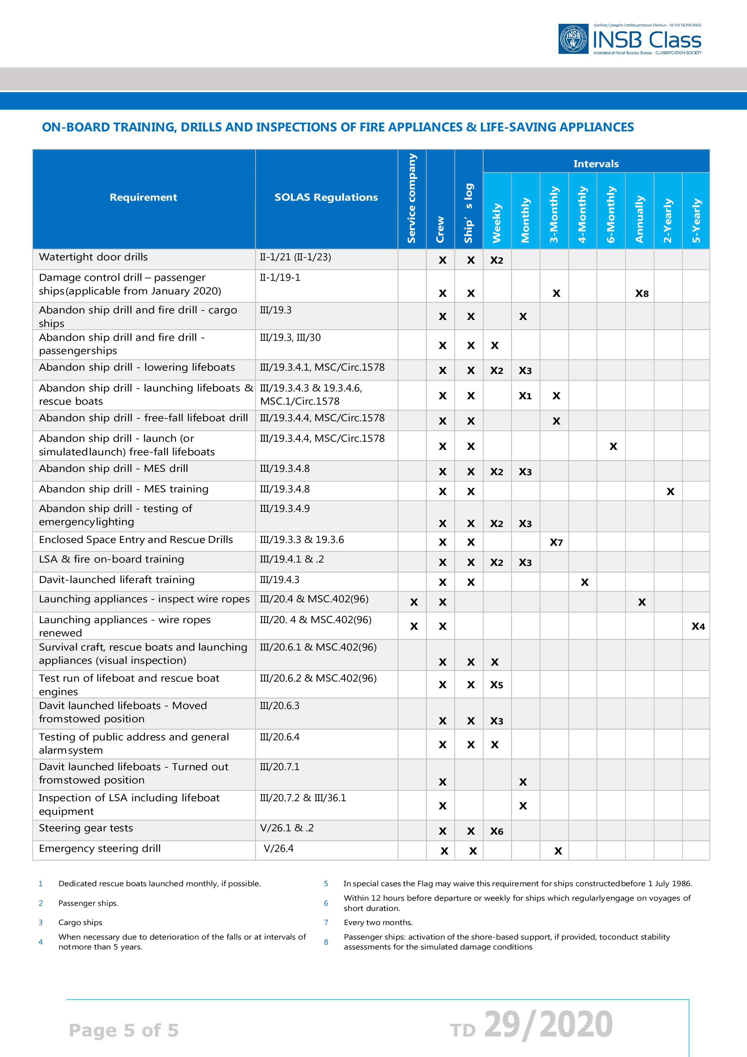
  • Every crew member shall participate in at least one abandon ship drill and one fire drill every month.
  • The drills of the crew shall take place within 24 h of the ship leaving a port if more than 25% of the crew have not participated in abandon ship and fire drills on board that particular ship in the previous month.
  • When a ship enters service for the first time, after modification of a major character or when a new crew is engaged, these drills shall be held before sailing.
  • It is a legal requirement that every crew member who is assigned to emergency duties is familiar with those duties before the ship sails. This requirement may also be found in the STCW Convention and in the requirements of the ISM code.
  • In passenger ships, whenever passengers are to be on board for 24 hours or longer, there must be a muster of passengers within 24 hours of their joining at which time they are to be instructed in the use of lifejackets and the actions to be taken in any emergency. In general this muster should take place, whenever possible, before the ship sails.
  • Whenever a new passenger or passengers join there shall be a passenger briefing before the ship sails made through the public address system or a similar effective system and supplemented if appropriate by video display facilities and similar.
  • The briefing should cover the items required in the emergency instructions for passengers and be in English and also in any other language likely to be used by a majority of the passengers.
 
Lifeboats lowered by means of falls
  • During drills, everyone participating should be alert for potentially dangerous conditions or situations and should bring them to the attention of the responsible person for appropriate action.
  • When drills are to be performed with persons on board the lifeboat, it is recommended that the boat be lowered and recovered without any persons on board first to ascertain that the arrangement functions correctly.
  • In this case, the boat should then be lowered into the water with only the number of persons on board necessary to operate the boat.
  • To prevent lashings or gripes from getting entangled, proper release should be checked before swinging out the davit.
 
Free-fall lifeboats
  • The monthly drills with free-fall lifeboats should be carried out according to the manufacturer's instructions, so that the persons who are to enter the boat in an emergency are trained to embark the boat, take their seats in a correct way and use the safety belts; as well as being instructed on how to act during launching into the sea.
  • When the lifeboat is free-fall launched as part of a drill, this should be carried out with the minimum personnel required to manoeuvre the boat in the water and to recover it.
  • The recovery operation should be carried out with special attention, bearing in mind the high-risk level of this operation.
  • Where permitted by SOLAS4 , simulated launching should be carried out in accordance with the manufacturer's instructions, taking due note of the Guidelines for simulated launching of free-fall lifeboats.

SOLAS regulation III/19.3.3.4 requires that lifeboats for free-fall launching be launched by free-fall every six months with its assigned operating crew on board. During such launching, only the persons who are to manoeuvre the boat in the water should be on board.  The same SOLAS regulation gives the Administration a possibility of extending the interval between the launching of lifeboats by free-fall to 12 months provided that an arrangement is provided for simulated launching every six months.


Conduct of drills – typical simulated launching sequence (SOLAS regulation III/19)
  • Check equipment and documentation to ensure that all components of the lifeboat and launching appliance are in good operational condition.
  • Ensure that all personnel involved in the drill are familiar with the operating manuals, posters and signs.
  • Ensure that the restraining device(s) provided by the manufacturer for simulated launching are installed and secure and that the free-fall release mechanism is fully and correctly engaged.
  • Establish and maintain good communication between the assigned operating crew and the responsible person.
  • Disengage lashings, gripes, etc. installed to secure the lifeboat for sea or for maintenance, except those required for simulated free-fall.
  • Participating crew board the lifeboat and fasten their seatbelts under the supervision of the responsible person.
  • All crew disembark the lifeboat.
  • Return the lifeboat to the condition it was in prior to step provided in paragraph 3.4. Ensure that the lifeboat is returned to its normal stowed condition. Remove any restraining and/or recovery devices used only for the simulated launch procedure.
 
Marking, periodical operation and inspection of watertight doors, etc., in passenger ships
  • Drills for the operating of watertight doors, sidescuttles, valves and closing mechanisms of scuppers, ash-chutes and rubbish-chutes shall take place weekly.
  • In ships in which the voyage exceeds one week in duration a complete drill shall be held before leaving port, and others thereafter at least once a week during the voyage.
  • All watertight doors, both hinged and power operated, in main transverse bulkheads, in use at sea, shall be operated daily.
  • On-board training in the use of the ship’s fire-extinguishing systems and appliances shall be planned and conducted in accordance with the provisions of regulation III/19.4.1.
  • Fire drills shall be conducted and recorded in accordance with the provisions of regulations III/19.3 and III/19.5.


Helicopter facilities

The purpose of this regulation is to provide additional measures in order to address the fire safety objectives of this chapter for ships fitted with special facilities for helicopters. For this purpose, the following functional requirements shall be met:

  • helideck structure must be adequate to protect the ship from the fire hazards associated with helicopter operations;
  • fire-fighting appliances shall be provided to adequately protect the ship from the fire hazards associated with helicopter operations;
  • refuelling and hangar facilities and operations shall provide the necessary measures to protect the ship from the fire hazards associated with helicopter operations; and
  • operation manuals and training shall be provided.

  A helideck shall be provided with both a main and an emergency means of escape and access for fire fighting and rescue personnel. These shall be located as far apart from each other as is practicable and preferably on opposite sides of the helideck.


Operations manual and fire-fighting service
  • Each helicopter facility shall have an operations manual, including a description and a checklist of safety precautions, procedures and equipment requirements. This manual may be part of the ship's emergency response procedures.
  • The procedures and precautions to be followed during refuelling operations shall be in accordance with recognized safe practices and contained in the operations manual.
  • Fire-fighting personnel, consisting of at least two persons trained for rescue and fire-fighting duties, and fire-fighting equipment shall be immediately available at all times when helicopter operations are expected.
  • Fire-fighting personnel shall be present during refuelling operations. However, the fire-fighting personnel shall not be involved with refuelling activities.
  • On-board refresher training shall be carried out and additional supplies of fire-fighting media shall be provided for training and testing of the equipment.


Fire Drills
  • Fire drills have caused accidents, and for this reason all elements involving unnecessary risks should be left out of such drills. Here are some examples:
  • When watertight doors are closed, there might be a risk of persons getting jammed in the doors that are closing with great force. For this reason, watertight doors should not be closed by means of remote control during drills.
  • The remote controlled release of fire doors can also involve a risk of personal injury. Before fire doors are remote released, a warning hereof should, insofar as possible, be announced on the public address system.
  • Some ships are provided with an arrangement for the recovery of a hoist stretcher, for example from the pump room. Training of the recovery of a hoist stretcher should be carried out without persons on the stretcher. A similar load can be used instead.
  • Darkening the glass of the smoke-helmet can, for example, simulate reduced visibility caused by smoke. This makes it possible for a person who can see to walk next to the fire-fighter with reduced visibility and interfere if the fire-fighter is about to get into trouble.


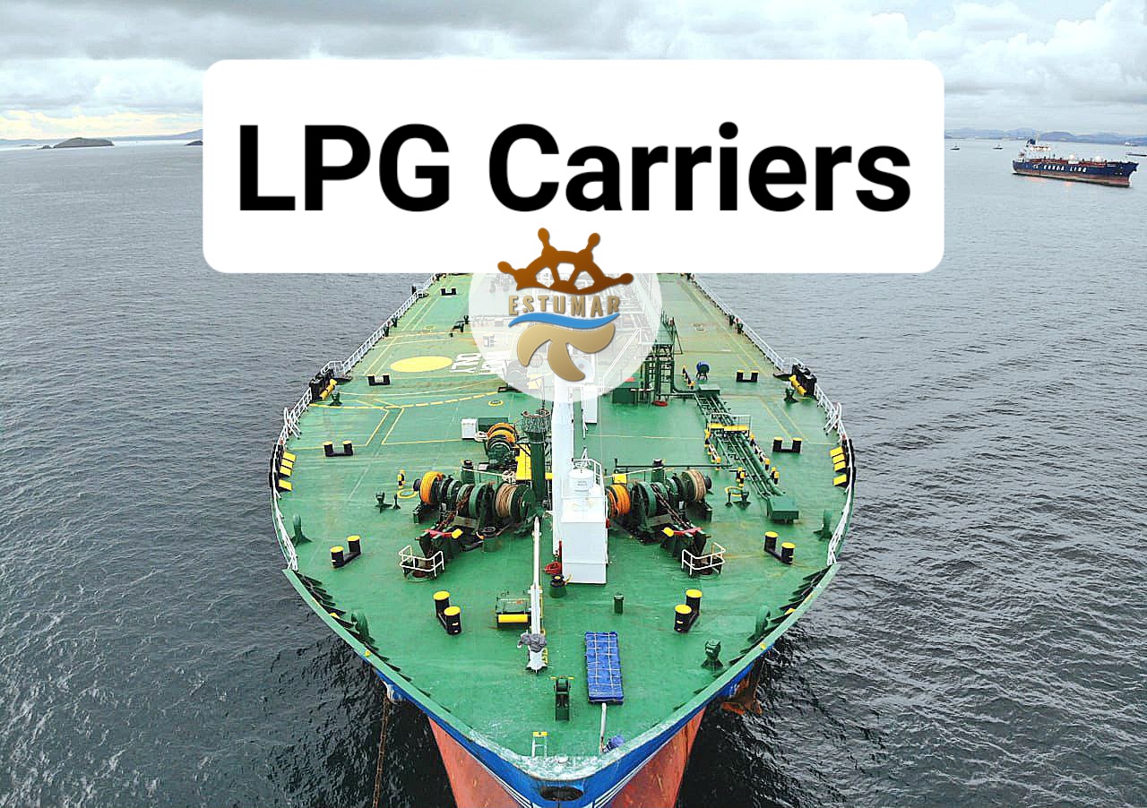
LPG (Liquefied Petroleum Gas) vessels are specialized ships designed for the transportation of liquefied gases, primarily propane and butane. LPG is a valuable energy source used for various purposes, including heating, cooking, and as a fuel for vehicles. LPG vessels play a crucial role in the safe and efficient transport of these gases from production facilities to distribution centers and end-users.

Working on LPG vessels can be safe when the crew diligently follows all safety precautions and regulations. These ships are designed and operated with a strong emphasis on safety due to the nature of the cargo they transport, which includes highly flammable and potentially hazardous gases.

When all of safety precautions and regulations are followed diligently, the risks associated with working on LPG vessels are minimized, and the safety of the crew, the vessel, and the environment is well-preserved. Safety is paramount in the maritime industry, especially when dealing with hazardous cargo, and it requires a collective effort from the crew, shipping companies, and regulatory authorities to maintain these high standards of safety.

LPG vessels are primarily designed for the transportation of liquefied gases, particularly propane and butane. However, these vessels can transport a variety of other liquefied gases and chemical cargoes depending on their design and the required safety and containment measures. Some specific cargoes that can be transported on LPG vessels include:

  • Propane (C3H8): Propane is one of the most common cargoes carried on LPG vessels. It is widely used for heating, cooking, and as a fuel for vehicles.
  • Butane (C4H10): Butane is another common cargo transported on LPG vessels. It is used for heating and as a fuel, and it can be blended with propane for specific applications.
  • LPG Mixtures: LPG vessels can carry mixtures of propane and butane, often referred to as "autogas" when used as a vehicle fuel.
  • Ammonia (NH3): LPG vessels can transport ammonia, which is used in various industrial applications, including refrigeration and as a fertilizer.
  • Chlorine (Cl2): Chlorine, a hazardous cargo, can be carried in specialized containers on some LPG vessels. It is used in water treatment and as a chemical feedstock.
  • Pentane (C5H12): Pentane is used as a propellant in aerosol products, a blowing agent in the foam insulation industry, and as a fuel in some applications.
  • Propylene (C3H6): Propylene, a petrochemical, is used in the production of plastics, chemicals, and fuels.
  • Ethylene (C2H4): Ethylene is another important petrochemical used in the production of plastics, chemicals, and as a refrigerant.
  • Butadiene (C4H6): Butadiene is a chemical used in the production of synthetic rubber and plastics.
  • Isobutane (i-C4H10): Isobutane is used as a refrigerant and in the production of petrochemicals.
  • Vinyl Chloride (C2H3Cl): Vinyl chloride is a chemical used in the production of polyvinyl chloride (PVC) plastics.
  • Ethyl Chloride (C2H5Cl): Ethyl chloride is used in various applications, including as a refrigerant, a propellant, and a local anesthetic.
  • Propylene Oxide (C3H6O): Propylene oxide is a chemical used in the production of polyurethane foams and glycol antifreeze.

It's important to note that transporting hazardous and flammable cargoes, including those listed above, on LPG vessels requires strict adherence to international safety regulations, proper containment, and safety measures to prevent accidents and protect the crew, vessel, and the environment. Shipping companies and seafarers must follow stringent safety protocols to ensure the safe transportation of these cargoes.

Here's an overview of how LPG vessels work and the process for seamen working on them:

  • Vessel Types: LPG vessels come in different types, including fully pressurized ships and semi-pressurized/fully refrigerated ships. Pressurized vessels carry LPG under high pressure in cylindrical tanks, while refrigerated vessels store LPG in low-temperature conditions, maintaining it as a liquid.
  • Loading and Unloading: Seamen on LPG vessels are responsible for loading and unloading LPG cargo. This involves connecting hoses, pumps, and valves to transfer the liquefied gas to or from onshore terminals or other vessels.
  • Safety Precautions: Safety is paramount on LPG vessels. Seamen must adhere to strict safety protocols and standards to prevent accidents and ensure the safe transportation of the cargo. This includes fire safety measures, handling emergency situations, and using personal protective equipment.
  • Cargo Handling: Seamen need to monitor the cargo's temperature, pressure, and other critical parameters to maintain its integrity. They may need to adjust the vessel's refrigeration or heating systems accordingly.
  • Navigation: Navigation and maintaining the vessel's stability are vital. Seamen work closely with the ship's officers to ensure the vessel is on the right course and that it maintains a steady balance, especially in rough seas.
  • Maintenance: Routine maintenance of equipment, engines, and safety systems is essential. Seamen are responsible for maintaining and repairing various ship systems to ensure the vessel's operational efficiency.
  • Documentation: Proper documentation of cargo operations, safety inspections, and maintenance records is crucial. Seamen must maintain accurate records as per international regulations.

When considering a future career on LPG vessels, here are some key perspectives to keep in mind:

  • Training: To work on LPG vessels, individuals typically need specific training and certifications, including STCW (Standards of Training, Certification, and Watchkeeping for Seafarers) and Gas Tanker Familiarization. Ongoing training and education are essential to keep up with industry advancements.
  • Safety Awareness: Safety is a top priority on LPG vessels. Aspiring seamen should have a strong commitment to safety procedures and be willing to follow rigorous safety protocols.
  • Career Progression: A career on LPG vessels can provide opportunities for advancement, from entry-level seamen to officers and engineers. Consider your long-term career goals and the required education and experience to achieve them.
  • Work-Life Balance: Be prepared for a seafaring lifestyle that often involves long periods away from home. Consider how this fits with your personal and family life goals.
  • Industry Outlook: Research the LPG shipping industry to understand its current trends and future prospects. The demand for LPG as an energy source and its role in the transition to cleaner fuels may impact the industry's growth.
  • Networking: Building a network in the maritime industry can be valuable for career advancement. Joining professional organizations and attending industry events can help you connect with peers and employers.
  • Environmental Considerations: As the world shifts towards more environmentally friendly energy sources, consider the industry's sustainability efforts and how they align with your values and career aspirations.

In summary, a career on LPG vessels can be rewarding, but it requires a commitment to safety, training, and a willingness to adapt to the evolving needs of the industry. It's essential to plan your future career with a focus on education, safety awareness, and understanding the industry's current and future dynamics.

The goals and salary expectations for a career on LPG vessels can vary depending on several factors, including your level of experience, position on the ship, qualifications, and the shipping company you work for. Here are some common goals and salary expectations associated with a career in this field:

Goals:

  • Entry-Level Seafarer: If you're starting as an entry-level seafarer, your initial goals may include gaining experience and advancing to higher positions. This might involve acquiring necessary certifications and training to become more specialized in LPG vessel operations.
  • Certifications and Training: As you progress, your goals could include obtaining additional certifications and training to qualify for higher-ranking positions, such as becoming a deck officer or an engineer officer on an LPG vessel.
  • Career Advancement: Many individuals aim to climb the career ladder in the maritime industry. This can involve advancing from an Ordinary Seaman to Able Seaman, then to various officer roles (Third Mate, Second Mate, Chief Mate), and ultimately, becoming a Captain (Master) or Chief Engineer. Each step comes with increased responsibilities and higher salaries.
  • Specialization: Some seafarers may choose to specialize in specific areas, such as cargo operations, safety, or navigation. Specialization can lead to roles as a Cargo Officer or Safety Officer on LPG vessels.
  • Work-Life Balance: For some, the goal might be to find a balance between their seafaring career and personal life. This can include choosing specific types of LPG vessel jobs with shorter rotations or seeking employment with companies that prioritize work-life balance.
  • Long-Term Career Security: A goal for many seafarers is to have a long and stable career in the maritime industry, ensuring a steady source of income and job security.

Salary Expectations:

Salary expectations in the maritime industry, including LPG vessels, can vary widely based on factors such as experience, position, vessel type, location, and the shipping company. Here are some approximate salary ranges for different positions:

  • Entry-Level Seafarer (Ordinary Seaman or Deck Cadet): The starting salary for an entry-level seafarer can vary but may range from $20,000 to $40,000 per year.
  • Able Seaman: An Able Seaman can earn between $30,000 and $50,000 annually.
  • Officer Positions (Third Mate, Second Mate, Chief Mate): Salary for officers can range from $50,000 to $100,000 or more, depending on the rank and experience.
  • Captain (Master) or Chief Engineer: Captains and Chief Engineers are among the highest-paid positions in the industry. Their salaries can range from $100,000 to $200,000 or more annually.
  • Specialized Roles (Cargo Officer, Safety Officer): Specialized positions may command higher salaries, often similar to officer salaries.
  • Bonuses and Benefits: Some shipping companies offer bonuses, such as signing bonuses, retention bonuses, and profit-sharing, in addition to basic salaries. Benefits like accommodation, meals, and health insurance are usually provided while on board.

It's important to note that salaries can be significantly affected by factors such as the size and type of the vessel, the company's policies, your experience, the specific trade routes, and market conditions. Additionally, seafarers often work on a rotation system, with periods at sea and leave periods, which can affect their annual earnings. Overall, the goals and salary expectations for a career on LPG vessels can be lucrative, but they require dedication, hard work, and ongoing professional development.

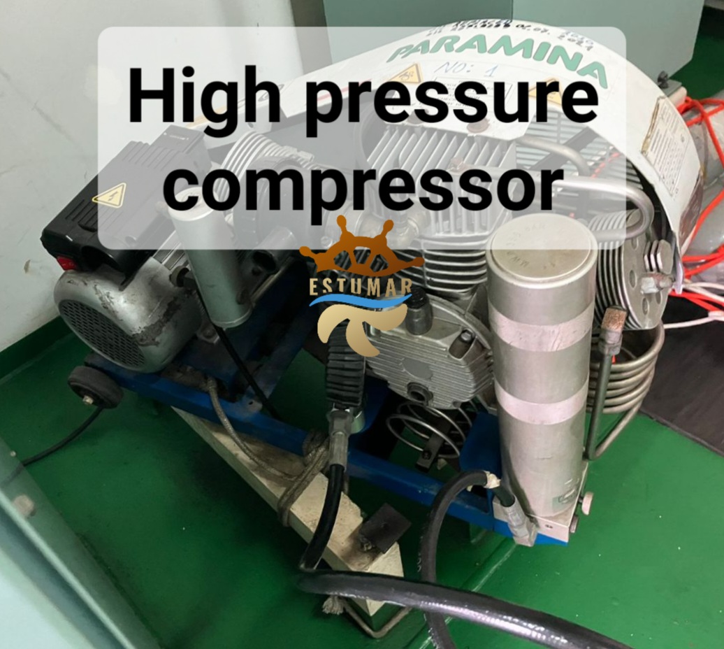
Previously, we reviewed the Marine air compressor, providing a brief explanation of what it is, its uses, and potential problems associated with such compressors. In addition to ordinary air compressors, high-pressure compressors are designed to ensure safety on board vessels.

High-pressure compressors on vessels are essential pieces of equipment used to generate and store compressed air at significantly elevated pressures. These compressors are typically designed to handle higher pressure levels than standard compressors and serve various critical functions on ships. Here are some common applications for high-pressure compressors on vessels:

Air Start Systems: Many larger vessels, particularly those with large diesel engines, use high-pressure compressed air to start the engines. High-pressure air start systems provide the necessary force to turn the engine's crankshaft.

Pneumatic Tools: High-pressure air is used to operate pneumatic tools and equipment for maintenance and repair work on the ship. These tools require compressed air at higher pressures to operate effectively.

Inert Gas Systems: High-pressure compressors are used in inert gas systems on certain types of ships, such as oil tankers. These systems maintain a blanket of inert gas (typically nitrogen) over flammable cargo to prevent fires and explosions.

Hydrostatic Testing: High-pressure compressors are used for hydrostatic testing of various equipment and systems on board, including pressure vessels, pipelines, and firefighting equipment.

Scuba and Diving Operations: In some cases, high-pressure compressors are used to fill high-pressure cylinders for scuba diving and underwater work, which require air at elevated pressures.

Breathing Air Systems: Vessels with enclosed spaces or hazardous cargo may require high-pressure breathing air systems to provide clean, high-pressure air for crew members and divers to use with breathing apparatus.

High-Pressure Gas Storage: High-pressure compressors are used to fill and maintain high-pressure gas storage cylinders on board, which can be used for various purposes, including emergency gas supplies.

Firefighting Systems: Certain firefighting systems on vessels may use high-pressure compressed air to operate, such as fixed fire suppression systems and firefighting foam equipment.

Since the high-pressure compressor is an important safety equipment and requires special attention in terms of maintenance time. They need to be maintained and operated in accordance with safety regulations to ensure the safety of the vessel and its crew. The following are examples of serviceable components:

- Oil replacement for oil every 500 hours or every 6 months.

- AC/MS Cartridge replacement every 20 hours or every 15 hours according the model of compressor 20 degrees ambient temperature or every 6 months.

- Coalescing pre-filter cartridge replacement every 200 hours or once a year.

- Air intake cartridge replacement every 200 hours or once a year.

High-pressure compressors on vessels are designed to withstand the harsh marine environment and the demands of continuous operation. Crew members responsible for their operation and maintenance often require specialized training.

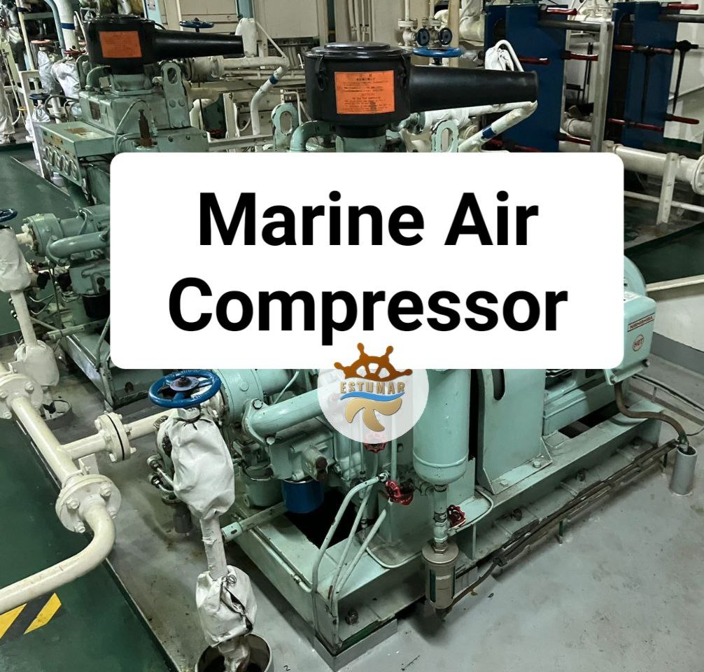
Marine air compressors play a vital role in the functioning of ships, providing the necessary air pressure for a wide range of tasks. These powerful machines are used across all types of vessels, contributing to essential operations that keep ships running smoothly.

Understanding the Role of Marine Air Compressors.

Marine air compressors, often overlooked but essential components, serve a multifaceted purpose. They work by decreasing air volume while increasing its energetic potential, delivering additional power to various onboard tasks. A ship's air compressor maintains the overall functionality of the vessel, from straightforward duties like filter cleaning and drying to the more critical tasks of starting auxiliary and main engines.

Built to Withstand Harsh Conditions.

Marine air compressors are constructed from sturdy materials that can withstand the demanding conditions of life at sea without warping. It is critical that these machines maintain their integrity, as using subpar air compressors could lead to device failure and even pose safety hazards.

How Air Compressors Function.

The fundamental principle behind air compressors is the compression of gas to increase its pressure while storing the compressed gas in a solid container or tank, typically equipped with pressure gauges and safety mechanisms. Compressors come in various types, including rotating, reciprocating, centrifugal, and screw-based designs.

Reciprocating compressors, similar in construction to internal combustion engines, feature a piston and cylinder arrangement. They incorporate inlet and outlet valves for normal air entry and the release of compressed air, along with other components like connecting rods and crankshafts. The more power a compressor needs to deliver, the greater the number of cylinders it typically possesses.

Diverse Applications on Ships.

Marine air compressors are versatile tools that serve multiple functions on ships, depending on their location. They are generally categorized into four main types:

  • Main;
  • Deck;
  • Emergency;
  • Topping Up.

Main Marine Air Compressor.

The primary marine air compressor serves as the power source for initiating both primary and auxiliary engines. It stores pressurized air, which is released to start the engines. Due to the significant power required for this task, the main marine air compressor typically boasts high capacity.

Deck Marine Air Compressor.

Deck marine air compressors are designed to be compact and portable, ensuring maximum mobility. This flexibility allows them to fulfill various functions on the deck, such as operating power tools for minor repairs or handling cleaning and sanitation tasks. In emergency situations on the deck, like fires, these compressors play a critical role in operating fire pumps, responding swiftly to maintain ship and crew safety.

Emergency Marine Air Compressor.

Emergency marine air compressors serve as backup power sources in case of power failures. They provide the necessary power to operate primary and auxiliary engines during potential power outages. Having at least one emergency air compressor onboard is essential to keep the ship's functionality intact.

Topping Up Marine Air Compressor.

Topping up marine air compressors are employed to compensate for any existing or potential leaks within a system. These compressors are connected to devices that monitor the system's current pressure. If the pressure falls below a specified level, the topping up marine air compressor can restore it to the desired level.

Troubleshooting Marine Air Compressors.

The marine air compressor system used onboard is of paramount importance to marine engineers, as it plays a crucial role in a ship's operation. Maintaining various components of the compressed air system, including compressors, pipelines, and air bottles, is vital.

To effectively troubleshoot common problems with air compressors, it is essential to understand all aspects of the system. Comprehensive checks should be conducted before operating the compressor. As a marine engineer, being able to identify and address common issues associated with marine air compressors is imperative.

Here are some common troubleshooting points for marine air compressors:

  1. Low Compressor Capacity.

Low compressor capacity is a prevalent issue, often resulting from prolonged operation without meeting air demand. Possible reasons for this problem include:

  • Leakage in discharge and suction valves.
  • Faults or leaks in the unloader.
  • Relief valve leaks.
  • Increased bumping clearance.
  • Incorrect compressor auto cut-in and cut-out settings (set too close).
  1. Oil Carry Over in Air.

If the compressed air contains oil, it could be due to:

  • Oil Water Separator is not working correctly hence oil is being carried to the air receiver;
  • The cylinder lubrication is adjusted at high quantity, leading to carryover of oil with air;
  • The auto drain is malfunctioning.
  1. Excessive Vibration and Noise.

Excessive noise and vibration from the compressor may be attributed to:

  • Loose pulley, flywheel, belt, belt guard, cooler, clamps or accessories;
  • Lack of oil in the crankcase;
  • Piston hitting the valve plate i.e reduced bumping clearance;
  • Compressor holding down bolts are loose;
  • Compressor foundation chocks have worn out.
  1. Overheating of Discharged Air

Overheating of discharged compressed air can be due to:

  • Clogged or dirty intercooler tubes.
  • Reduced or insufficient cooling water pump capacity.
  • Hot atmospheric air at the compressor's air suction.
  • Lack of forced ventilation for fresh air near the compressor.
  • Damaged head gasket.
  • Clogged air suction filter.
  • Leaking valves in the 1st or 2nd stage.
  1. Milky Oil in the Crankcase.

The presence of milky-colored oil in the crankcase may result from:

  • Water leakage from the cylinder liner or jacket.
  • Exceeded oil running hours.

These are some of the most common issues encountered with continuously running air compressors onboard ships. Understanding these problems and their possible causes is crucial for marine engineers to ensure the smooth operation of marine air compressors.

In the recent past the shipping industry has noted an increasing number of blackouts and main engine failures, which can result in a total loss of propulsion and steering capability. The risks to the vessel and crew become critical and may result in a major casualty when they occur while maneuvering in restricted areas (traffic lanes, channels), entering or leaving port or navigating close to a coast during heavy weather.

Total blackouts have occurred on vessels that operate either with a common power system configuration or with the power system split into two or more independent power systems. It is more prevalent in the former configuration. In the latter configuration, internal and external common cause failures are often the cause rather than individual equipment failures. Not all causes of vessel blackout can be recovered from – i.e. there may be some scenarios where recovery will not succeed even if it operates correctly. Success depends on whether the common cause failure that initiated the blackout remains active. Where recovery includes restart of generators, drives, major consumers and auxiliary services, the success of blackout recovery often depends on the absence of active lockout functions on the Main Switchboards, thruster drives restart time etc.

The primary aim of this paper is to:

• Review the various blackout recovery test procedures that are sometimes performed as part of annua trials and to evaluate their effectiveness in replicating a real blackout condition;

• Present an additional test procedure that could be performed to improve the effectiveness of Blackout Recovery Testing;

• Investigate the impact that any additional blackout recovery tests would have on equipment longevity;

• Identify system components and methodologies that could be incorporated into existing and future designs to facilitate blackout recovery tests – Build To Test.

The additional test proposed is considered as an enhancement of the existing tests that may already be performed as part of blackout recovery testing. Furthermore, the tests are not aimed specifically at any particular equipment manufacturer as the tests aim to replicate failures that could be experienced on any vessel regardless of equipment manufacture and design. However, the implementation of the test circuit may vary depending on the equipment type.

Consequences of Propulsion Loss.

The most serious consequences of a blackout or propulsion loss are contact, collision and/or grounding.

Grounding.

Furthermore, a significant number of claims for third party property damage, many of which were enormously expensive, could be attributed directly or indirectly to main engine failures or electrical blackouts.

Possible Causes of Propulsion Loss.

According to a detailed analysis of claims related to propulsion loss by UK P&I Club for a period of five (5) years, the main causes of propulsion loss are as follows:

• Insufficient or ineffective maintenance

• Equipment failure

• Human error

• Fire

What are action in case of Blackout on the vessel?

In all emergencies, Captain/Chief Eng. will take control of situations as soon as possible – but initiative must be taken by other individuals where immediate action is required.

Sounding the alarm must be loud and clear – use of the General alarm and PA System is encouraged.

Any available spare person should be nominated as writer as soon as possible to prompt actions from this checklist and record events as they happen.

What must be done?

1. Do not move around in darkness

2. Allow auto start of stand by generator and auto restoration of power to main switchboard to take place. Do not interfere.

3. Observe automatic sequential restart of all essential auxiliaries. Do not interfere.

4. Check plant conditions and parameters

5. Check if power is restored to emergency switchboard. * If not, do so manually at the emergency switchboard. (Switch select mode to Manual, stop engine and close bus tie).

6. Start and parallel a second generator.

7. Bring bridge control to stop and then restart main engine to bridge requirements.

8. Start all non automatic restart auxiliaries.

9. Stop G/E electric gasoil pump.

10. Reset boilers electric failure trip at local board.

11. Check that emergency generator is stopped.

12. Establish cause of blackout and rectify.

13. Note position at time of failure & at power resumption

14. Change to Steering Mode One & Gyro One when EM switchboard up.

15. Engage manual steering and alter away from any danger

16. Call Master

17. Clear away anchors if near coast / shallow water.

Actions upon the Bridge.

This is unlikely to be a bridge only blackout. As soon as emergency generator starts steering will be regained vessel will still have sufficient speed to alter from close danger. In the event of a blackout on the Bridge, the following actions must be carried out immediately:

1.Call the Master to the bridge and inform him of the situation.

2. Display the Not Under Command lights/shapes.

3. Acknowledge all alarms.

4. Check for any traffic in the immediate vicinity. Should any vessel pose a threat then the whistle, Aldis lamp, and VHF may be utilised to mitigate the threat. If vessel is totally blacked out with no battery power then the SOLAS VHF walkie talkies may be utilised.

5. A SECURITE message may be transmitted if required – but not unless authorised by the Master

6. Check for the proximity of any navigational hazards.

7. Fix and record the vessels position – GPS operates on battery mode.

8. Additional manning to the Bridge if required.

9. Engage manual steering and steer away from the nearest hazard. Note that with the emergency generator you can use the port steering motor – No 2.

10. If time permits switch radars to standby mode, and computers off.

11. Liase closely with the Engine Room as to the cause of the blackout and as to the expected duration of any maintenance prior to normal services being resumed.

12. If the blackout looks to be prolonged, and if conditions so warrant it, consider the use of anchors, and call relevant manpower.

13. A concise and chronological recording of events in the Deck Operations Log is required.

14. Following due consultation with the Engine Room, put the telegraph back to the stop position since it will require resetting for Bridge Control functions. Engine Room

Control may be required.

15. Any tank entry must be immediately suspended and the work permit cancelled until the situation is resolved – all other work permits must be reviewed and action taken if so required.


Sometimes you can hear the term brownout. Brownouts and blackouts are both terms used to describe electrical power disturbances, but they have different characteristics and causes:

Brownout:

A brownout is a temporary and intentional drop in voltage in an electrical power system.

It is usually initiated by the power utility company to prevent a complete blackout during times of high demand or when there is a shortage of electricity.

During a brownout, the voltage supplied to electrical devices is reduced, causing them to operate at lower power levels.

Brownouts can result in dimmer lighting, slower motorized devices, and potential damage to sensitive electronic equipment.

The intention behind a brownout is to conserve energy and prevent overloading the electrical grid, rather than completely cutting off power.

Blackout:

A blackout, also known as a power outage, is a complete and unexpected loss of electrical power in an area or region.

It can occur for various reasons, including severe weather events (such as storms or hurricanes), equipment failures, grid overloads, or human errors.

During a blackout, all electrical devices and lighting in the affected area cease to function until power is restored.

Blackouts can last for a short duration, such as a few seconds or minutes, or they can extend for hours or even days, depending on the cause and the ability of the power company to restore service.

Blackouts can disrupt daily life, lead to economic losses, and in some cases, pose safety risks.

In summary, a brownout is a controlled and deliberate reduction in voltage to conserve energy and prevent a complete blackout, while a blackout is an unplanned and total loss of electrical power due to various factors. Both can have significant impacts on electrical systems and the daily lives of people in the affected areas.

Port State Control (PSC) is the inspection of foreign ships in national ports to verify that the condition of the ship and its equipment comply with the requirements of international regulations and that the ship is manned and operated in compliance with these rules.

Many of IMO's most important technical conventions contain provisions for ships to be inspected when they visit foreign ports to ensure that they meet IMO requirements.

A ship going to a port in one country will normally visit other countries in the region and it can, therefore, be more efficient if inspections can be closely coordinated in order to focus on substandard ships and to avoid multiple inspections.

This ensures that as many ships as possible are inspected but at the same time prevents ships being delayed by unnecessary inspections. The primary responsibility for ships' standards rests with the flag State - but port State control provides a "safety net" to catch substandard ships.

Port State Control in the USA Checklist (gas carriers).

Maneuvering data is to be posted on the bridge in USCG (United States Coast Guard) format. This must include the required warning notice.

The following tests are to be carried out not more than 12 hours before entering US coastal waters:

  • Steering gear and systems including alarms and indicators;
  • Internal communications and alarm systems;
  • Emergency generator and emergency fire pump with simultaneous charging of two fire hoses, one at the bow and one on the bridge wing;
  • Storage batteries for emergency lighting and power systems;
  • Main engine ahead and astern;
  • 95%; 98% tank alarms;
  • Operation of ESD bottoms.

The above tests are to be entered in the deck logbook.

Vessel must have appropriate charts and publications for the area to be transited and the port and these must be the latest editions and corrected to the most recent Notices to Mariners (In some ports, UK charts are not permitted and it is necessary to obtain the US charts for the area.

Clear instructions accompanied by a block diagram are to be posted in the bridge and steering flat for operation of the steering gear with instructions for change over to emergency steering operation.

Cargo Transfer Operations:

  • List of persons involved in each operation and their duties;
  • A list of actual names / ranks of those crew members responsible for cargo transfer procedures;
  • Chief officer standing orders in place;
  • The person in charge (PIC) for transfers of liquid cargo in bulk (C/O), and for transfers of fuel oil bunkers must be nominated(C/E). For foreign vessels, the PIC of a transfer of liquid cargo:
    a) Sufficient training and experience in the relevant characteristics of the vessel;
    b) The correct STCW license for rank issued by flag state;
    c) The relevant cargo endorsement if applicable;
    d) The capability of reading, speaking and understanding English;
    f) The capacity of communicating with all crewmembers onboard:
  • Approved by captain cargo plan available and signed.
  • Description of each operation giving schematic diagram of pumps, lines, valves etc.
  • Description / location of each shutdown device on relevant pumps / valves.
  • Procedure for topping off/stripping of the tanks.
  • Procedure for gassing up/cooling down/warming up/inerting/gas freeing of the cargo system.
  • Procedure for ensuring all valves used during the transfer closed on completion of transfer.
  • Procedure for operating emergency shutdown devices (ESD).
  • ESD system tested and operational. Records of test dates maintained. Manifold valves closing times correct.
  • An appropriate Material Safety Data Sheet (MSDS) for each grade of cargo being carried. Contact the office if it is not available onboard.
  • Cargo tank dome fittings in good condition. Operating pressures marked.
  • MARVS tested. Records of test available.
  • Temperature, pressure, level indicators in good condition. Certificates records of regular test available.
  • Deck eyewash’s and showers operational and clearly marked.
  • High level alarms working and date of last test available.
  • Fixed Gas Detection System operating. Calibration records and gas available.
  • Deck Spray system tested. Records of test available.
  • Cargo pumps tested. Records of test available.
  • Cargo pipe lines are to be tested at working pressure and the pressure and test date to be marked clearly on each line (Annual).
  • All portable gas measuring equipment calibrated. Records of calibration available.
  • All manifold spill trays are fitted with steel plugs and all deck scuppers are mechanically plugged, including poop scuppers.
  • Calibrated pressure gauges are fitted to all manifolds.
  • Ensure that all accommodation doors remain closed during cargo operations except for entry / exit.

Other records which are required are:

  • Safety equipment: check all firefighting equipment has been tested and is valid up to date. Have completed records ready for inspection.
  • Oil Record Books, class certificates and the most recent classification society survey report.
  • Ballast Water Management Plan and Log and relevant forms.
  • Garbage Log and records including receipts of disposed garbage.

The Master is to ensure that all staff are familiar with the requirements of the ISM Code since the U.S.C.G. inspectors may at any time, ask questions regarding the main elements of the code to ensure the vessel’s compliance. Ensure officer’s are aware of who the DPA is and the DPA’s responsibilities. The SOPEP or SMPEP must be approved by Flag State or Classification Society.

All SOLAS certificates must be valid with all annual inspections up-to-date. All Officers must have original licences as required by the Flag State onboard and be all ready for inspection. All officers and crew, as applicable, must have required special qualifications, e.g. dangerous cargo endorsements, hazmat, specific ECDIS training certificates etc.

Working hours pre-plan for all persons onboard has been prepared which complies with the Code of Federal Regulations governing working hour limitation. Records of working hours shall be available for inspection.

In addition to the above, we bring to your attention the following:

  • Make up procedure for enclosed entry procedure and post in prominent positions;
  • Ensure that all port and Company smoking regulations are in place;
  • Ensure all trading and type approved certificates are valid and ready for inspection;
  • Ensure that portable gas detectors are available for all watchkeepers;
  • Ensure that all officers are immediately identifiable to shore personnel;
  • That all alcohol is forbidden, REPEAT FORBIDDEN, in US waters. All alcohol is to be removed and placed under lock and key;
  • Place warning signs. (No visitors / unauthorised personnel / no smoking);
  • Sewage unit (MSD) or tank functioning correctly and certificate available;
  • Ensure that no hotwork is carried out.

Garbage management must strictly be in compliance with Company regulations. Large fines can be levied for incorrect storage and disposal of garbage and in particular plastics.

Be aware that the USCG inspectors are carrying out strict emergency drills, fire drills and full abandon ship drills and are picking crew members at random to start emergency fire pump, emergency generator and lifeboat engines. They will require one boat to be lowered into the water if safe and practical. The drills must be carried out promptly and in a satisfactory manner. Unsatisfactory drills account for in excess of 25% of detentions.

Ships with major deficiencies can be detained.

Port state control officers may impose a detention on ships with major deficiencies, it means that the ship couldn't leave the port of inspection. A ship is detained when it is unfit to proceed to sea or the deficiencies pose an unreasonable risk to the ship, its crew or the environment.

The ship is kept under detention until the rectification of all deficiencies has been verified by a port state control officer by means of a re-inspection.

An onboard inspection can only be successful if the tanker has been prepared for the inspection. For this reason, some companies perform pre-vetting inspections by internal resources prior to the vetting inspections by the oil majors. These inspections normally take place during discharge.

Most of the vetting inspectors are former seafarers with long experience from various types of tanker vessels. Most likely the first impression is formed already at the time the inspector arrives at the gangway and then continues all the way until the closing meeting have been completed. Inspectors will be looking for objective criteria by which to judge the tanker. Thus, the importance of the route from the ship side to the Master's office should not be underestimated. Remember that, as always, you do not get a second chance to make a first impression.

Make sure that each head of department has completed and signed off his own part of the vessel inspection questionnaire before arrival at port and that any deficiencies have been reported/corrected. This should be incorporated into the normal routine guidelines.

Although it is the Master's overall responsibility to prepare for an inspection, this is a teamwork involving all crew members.

Vetting Inspection Plan.

Operator of the ship schedules vetting inspection. Vessel receive details of inspection such as date of inspection, port of inspection, etc.

Inspection Prior to Boarding.

-Vetting inspector check the condition of external hull, superstructure, mooring lines laying, draft marks, overboard discharges, ship’s gangway, etc.

Pre-inspection Meeting (Open meeting).

  • Formal presentations of Auditor Inspector with Master and other senior officers;
  • Explain purpose of the present inspection and discuss the order of inspection with Master, Chief Officer & Chief Engineer;
  • Sequence of the inspection : Documentation check, Bridge inspection, outside accommodation inspection, lifeboat and rescue boat inspection, compressor room/motor room inspection, sighting from top or entering inside with one or two ballast tanks, rounds in forecastle deck, Cargo Control Room (CCR), Ship’s Hospital, Galley and Engine Room, followed by final meeting.

>Documentation Checks ( c/out with Master and C/O).

  • Trading certificates (Certificate of Registry, Safety Equipment, Safety Construction, Safety Radio, IOPP, etc);
  • Certificates of Test/Service: Life/Rescue boat and davit, Liferaft annuals, EEBD test, Portable and Fixed Fire extinguisher systems (Dry Powder & CO2 stations), Immersion suits, EPIRB, VDR, LRIT Test, Portable gas detector equipment;
  • PSC inspection reports;
  • Class records: Class attendance reports, ESP file;
  • LSA & FFA weekly & monthly checks;
  • Master’s Review of SMS and Safety meeting feedback;
  • Approved manuals- SMPEP, SEEMP, STS plan, Ballast & garbage management plans, Intact & Damage Stability booklet, P&A manual, LSA and FFA training manual, operations manual;
  • Type approval certificates: ECDIS, PMS approval certificates;
  • Crew certification, Work and rest hours;
  • Verify operator’s SMS against VIQ elements: Hot work, Alcohol policy, Smoking Policy, smoking areas, Enclosed space, PPE matrix, Lube oil analysis frequency, UKC policy, Tank inspection interval, NC close out policy, Emergency procedures;
  • Compliance checks: Alcohol policy compliance, Smoking policy, Permit to work system – Hot work, encloses space permits, working over side and aloft, Tank inspection records, Risk Assessments, PPE matrix, Non-conformity control, Safety meeting and drill records, Alcohol check records;
  • Cargo & Ballast tanks inspection records including void spaces;
  • Lifting gear register & Mooring ropes, Wires & sling certificates;
  • Non conformity & Incident reports;
  • Cargo record book, Garbage record books;
  • Ballast water management files & records;
  • PMS records, Pressure test record of cargo & Fuel Pipes;

Bridge Navigational Inspection  (c/out with 2/O).

  • Passage plan, chart and publication checks, navigation related records & checklists;
  • Navtex, T&P corrections;
  • Paper charts/ ECDIS for at least the whole of the last voyage;
  • Check the condition of the Radio station equipment, VHF, MF & HF;
  • Condition of SAT-C;
  • Request for Master Standing order and night orders;
  • Navigation procedures;
  • Review Bridge Posters;
  • Review Log books: Deck log, Compass error log, Radar ops log, GMDSS log);
  • PMS related to Navigation equipment & related spares, day signals etc.;
  • Emergency equipment on the bridge (LTA, EPIRB, para-rockets, MOBs, GMDSS radio & batteries);
  • Bridge wing and monkey island- antenna and lighting checks;
  • Switch ON lighting;
  • Cargo Tanks related panel. (Indication of Pressure, Temperature, Alarms);
  • IG panel (02 & pressure);
  • Fire fighting panel, Echo sounder, Course recorded marked-24hrs mode. AIS, VDR- save function, BNWAS test, GPS anchor alarm;
  • Navtex station, SAT C Nav warnings;
  • Night rounds system, Look out, Fire drill in log book.

Accommodation External Decks Inspection  (c/out with 3/O and C/O).

  • Bridge Wings & Monkey Island;
  • MOB Buoy condition;
  • EPIRB & SART;
  • Safety Signs for antenna’s;
  • Antenna ID & Earth connection;
  • Magnetic compass;
  • Check condition of Battery lockers;
  • All Deck emergency lighting;
  • Check funnel flaps test closing;
  • Emergency Generator test;
  • Starting of Lifeboat Motor after permission from terminal;
  • Life raft, ladders, IMO symbols;
  • Rescue boat;
  • Muster stations;
  • LSA/FFA Lockers & Fire man’s outfits;
  • Test Emergency generator after permission from terminal;
  • SCBA compressor room;
  • Air condition Room intake;
  • CO2 Room.

Aft Deck Inspection (c/out with C/O).

  • Check operation and condition of mooring equipment: winches, brake condition, ropes;
  • Check condition of all and vent heads.

Main/Forward Deck Inspection (c/out with C/O).

  • Rounds start with mooring, deck aft, then proceeding toward cargo main deck area;
  • Check condition of cargo pumps, cargo compressors, cargo condensers, cargo heater, etc.;
  • Check condition of level gauges, pressure & temperature gauges, piping, cargo tank PV Valves, lighting, ventilation, etc.;
  • Check condition of fixed (Seawater Spray & Dry Powder Stations) and portable fire fighting appliances (FFA);
  • Check condition of fire isolation valves;
  • Inert gas system (IGG) or Nitrogen system;
  • Manifold arrangement;
  • SMPEP gear;
  • Eyewash showers test;
  • Cargo related equipment: Manifold arrangement, Hose handling crane;
  • Inspect one or two ballast tank from top or inside, if permission from terminal available;
  • Fire line to be pressurized during inspection;
  • Check condition of the Forecastle space, Bow thruster space.

Cargo Control Room (CCR) Inspection  (c/out with C/O).

  • Check condition of the CCR equipment, pressure/temperature indicators, Pump indications, High Level Alarms, Cargo Tanks High Level Override switches, Cargo Tank Level Indications;
  • Check cargo plan, checklist, PMS, manuals, etc.;
  • Pre-cargo check list;
  • Other cargo and maintenance related documents, Port log;
  • Chief Officer Standing orders;
  • Pre-arrival test & Ship Shore Safety Checklist;
  • Check the condition of Portable Gas Monitoring Equipment;
  • Stability Computer;
  • Enclosed space records;
  • Piping plans;
  • MSDS.

Internal Accommodation Inspection  (c/out with C/O or OOW).

  • Check condition of Galley, portable and fixed fire extinguishing systems;
  • Smoke rooms, Mess rooms, SOLAS training manual, smoking notices etc.;
  • Refrigerated rooms doors, alarms;
  • Check condition of Laundry;
  • Check condition of Hospital and medicines;
  • Air condition room.

After-inspection meeting (Closing Meeting).

  • Discuss observations with Master, Chief Engineer and Chief Officer;
  • Conclude the inspection.

The results from a vetting inspection will give the oil major information needed to decide if the vessel is accepted for use. When the vetting inspector leaves the gangway, the vessel inspection is finalized. However, only than the screening process begins, and the owners reply to any comments or deficiencies raised play a very important part in this screening process.

Some examples of replies that do not live up this standard are e.g., "The deficiency has been rectified", "we have instructed the Master not to do it again", "the spare part has been ordered", etc.

In order to indicate that you have an effective system in place it is necessary to address the deficiency within the ISM system, for example by identifying the non-conformity, establishing the root cause and implementing an effective corrective action as well as necessary changes to existing procedures. The deficiency then becomes effectively closed out.

It is not sufficient to say that the deficiency has been fixed, you need to explain that the problem that caused the deficiency is also fixed.


The pilot ladder is a specialized rope ladder employed for the boarding and disembarking of pilots and crew members during various ship operations. The steps of the ladder are made of hardwood except the lower four steps are made of rubber.

The safety of pilot ladder usage relies on a complex chain of regulations, recommendations, industry standards, and procedures. Should any of these elements fail, the entire safety system could collapse, potentially resulting in severe and fatal consequences.

Given the unique characteristics of each vessel's construction, the correct method for rigging the ladder can vary significantly for each ship.

A Matter of Safety.

The safety of all pilots and crew members hinges on maintaining proper procedures when it comes to pilot ladder steps. The goal is for everyone to return home safely. Pilots come aboard vessels to support the ship's crew during critical and potentially hazardous navigation phases. Tragically, there have been instances where pilots have lost their lives or suffered injuries due to accidents during boarding and disembarkation procedures.

To prevent such incidents, it is imperative that the ship's crew and officers undergo training on the correct installation of a compliant pilot ladder and the rigging thereof, ensuring that they meet established standards and requirements.

Convention compliance:

- SOLAS Ch v Regulation 23;

- IMO resolution A. 1045 (27);

- IMO MSC 1428;

- IMO MSC 1495;

- ISM chapter 10;

- ISO 799-1.

Certificate and Marking:

Each pilot ladder should have a certificate in accordance with SOLAS Ch V Reg 23.2.1 and ISO 799:2004 standard.

Certificate contents:

  • Name of the manufacturer;
  • certifying body;
  • SOLAS approval;
  • type pilot ladder or embarkation ladder;
  • production date;
  • onboard date (must be entered by ship staff).

Certificate and Expiry Date:

  • Pilot ladders made to ISO 799 standards must undergo a strength test every 30 months, or the certificate must clearly state the expiration date.

Identification:

  • Every pilot ladder used for pilot transfers must bear unique identification tags or markings to facilitate surveys. Tags must be affixed at the bottom of the first step and the last spreader, containing essential information.

Hull Marking:

  • Recommended hull markings consist of white over red, with a width of 0.5 meters. The top two meters should be white, while the bottom two meters should be red. The positioning of the white mark's bottom indicates its proper alignment.

Ladder Design:

  • The 9-meter freeboard step must be constructed as a single piece of hardwood without paint or varnish to prevent slipperiness. The lower four steps must be made of rubber.
  • Step dimensions should be 400mm between side ropes, 115mm in width, and 25mm in thickness, with equal spacing between 310mm to 350mm.
  • If the ladder has more than five steps, it should include a spreader of 180cm length. The maximum number of steps between spreaders is nine, with the fifth step serving as a spreader.
  • All steps must remain horizontal and have metal tags at the bottom of the first step and last spreader. The replacement of steps should not exceed two in number.

Side Ropes:

  • Two uncovered ropes, each not less than 18mm in diameter, should run continuously on each side, made of manila rope or equivalent with a breaking strength of 24 kg to kN.
  • Side ropes should not form a loop at the bottom, and man ropes on both sides of the pilot ladder must be rigged upon the request of the pilot only.
  • A 28mm to 32mm diameter retrieval line is optional but, if fixed, must be positioned above the last spreader and led forward.

Ladder Mounting:

  • Both ladders must comply with an open-bottom model and should be securely clamped. The length of side rope below the final steps should not be less than 5cm, with a diameter not less than 32mm.
  • The distance between two stanchions should be within the range of 0.7 to 0.8 meters, with stanchion height at 1.2 meters above the bulwark.
  • Stanchions and rigid handrails should be present on both sides of the ladder and platform, but if hand ropes are used, they should be taut and properly secured.

Pilot Ladder Winch Reel:

  • Pilot ladder winch reels offer an efficient means of storing and moving the ladder. These are usually installed on the ship's upper main deck or at side openings, such as side doors, gangway locations, or bunkering points.
  • Winch reels on the upper deck may result in very long pilot ladders, embarkation platforms, or trapdoors.

Minimum Climbing Height:

  • The minimum climbing height for a pilot ladder ranges from 1.5 meters to 9 meters. This range is chosen because after three steps, there may be nothing to hold onto, and falling from heights greater than nine meters poses significant risks.

Gangway Platform:

  • The horizontal platform of a gangway should be no less than five meters above water level. During combination rigging, the pilot ladder must extend 2 meters above the platform.
  • The pilot ladder must be secured to the hull at a distance of not less than 1.5 meters from the gangway platform.
  • The horizontal distance between the gangway platform and the pilot ladder should be between 0.1 to 2 meters, and the ladder should not be tied to the gangway.
  • The angle of the gangway should be less than 45 degrees.


Often, seafarers are trying to get on gas fleet without any understanding what awaits them and because of this, vessels receive a lot of observations during inspections, losing their potential charters and the company loses its credibility at the international market.

Did you know that with the entry into force of SIRE 2.0, special emphasis will be placed on the knowledge of junior officers of key procedures regarding cargo operations, as well as the overall safety of the vessel. Now inspectors will interview officers more thoroughly in order to understand their general level of knowledge of basic procedures. Here is the simplest question for you to test your strength, which was asked to my 3rd officer by an English inspector from Exon Mobile, as an example of upcoming questions on SIRE 2.0:

What is the procedure for preparing a vessel for cargo operations? It seems to be an easy question, but ask yourself if you can answer it off the top of your head without resorting to any sources?

Remember that during the inspection you will be one on one with the inspector and you should have a clear picture and sequence in your head of every action the vessel will undertake before arrival and immediately before the commence of cargo operations.

You can focus on company’s SMS and to learn all cargo procedures and checklists (before/after loading/discharging), you can also find useful information in the following publications: 

Liquified Gas Handling Principles (LGHP4) in chapters:

  • The Ship/Shore Interface
  • Cargo Handling Operations

Tanker Safety Guide (Liquified Gas) in chapter:

  • Cargo Operations.

The best option for me, to prepare all cargo checklists in a separate file, so you can quickly run through the main points before passing the inspection. Now let's consider the main issues for preparing a vessel for cargo operations.

Before the vessel arrives at the port, the captain is obliged to request the following information through the agent of the port of loading:

  • The name and quantity of the cargo to be loaded (if there are several grades, the necessary information must be provided for each cargo).
  • Density and temperature of incoming cargo and any other necessary information.
  • Manifold operational pressure and temperature.
  • Requirements for inhibitors (if applicable).
  • Size and type of shore connection (ANSI, DIN).
  • Which side will be alongside, to prepare reducers (if required) in advance.
  • Availability on the terminal and the need of using shore vapour return line, and if applicable maximum performance figures.
  • Maximum operational rate and any restrictions if applicable.
  • Tidal and draft limitations.
  • Method of line clearing (N2 from shore to ship/ hot gas from ship to shore, etc)
  • Any special requirements of the terminal during cargo operations. An example is cargo sampling throughout the entire cargo operation after 25٪;50٪;75%;100%;

Prior arrival of the vessel, the following vessel’s safety systems and cargo equipment to be checked:

  • Emergency shut down systems (ESD). Check testing requirements for your vessel in your company PMS, but normally at least 3 activation buttons (on the side of the Manifold of cargo transfer, CCR an one other activation point) should be tested.
  • Firefighting and Safety systems (Fire hoses, Dry powder system, Eye wash, etc).
  • Fixed gas detection system. Check that all gas detection systems and sampling points are calibrated for the proper gas.
  • Cargo Manifolds and Cargo tanks filling valves. Closing time of cargo Manifolds hydraulic valves should be less than 30 seconds (normally between 25‐30).
  • High, High High and overfill system alarms (95%;98%99%) for the each cargo tank.
  • High and low pressure alarms for the each cargo tank.
  • Cargo Tank Relief Valve Set Pressure. As example for fully refregirated vessels - Primary Set Pressure (0.275 barG), Secondary Set Pressure (0.45 barG).
  • Ballast system hydraulic valves (open/closing time).
  • Fusible plugs (visual check/simulation test depends on your type).
  • Cargo holds P/V Valves and pressure inside cargo holds (if applicable).
  • Water spray system (especially for USA ports).

It is necessary to make entries about carrying out the above checks/tests to the vessel’s logbook, as well as you should be prepared for the fact that you may be required to provide evidence of each check/test.

Before commence of cargo operations, it is necessary to check the equipment that ensures the safety of the crew:

  • Deck illumination (especially Emergency illumination in cargo area).
  • Ventilations systems for cargo machinery and accommodation.
  • Communication equipment (CCR VHF, Hot line, etc).
  • Availability of personal protective equipment and readiness of breathing apparatuses.
  • Coordination of all works that could be performed in the area of cargo operations (lifting operations, bunkering, etc).
  • SOPEP equipment should be placed in cargo manifolds area.
  • Condition of the fire/protection screens (vent masts).
  • To familise the crew with the main dangers of the cargo declared for transportation (MSDS).
  • Post Safety Data Sheets (CCR, various decks, fire plan, etc).
  • Prepare portable gas detector for every person involved in cargo operation (zero/span calibration).
  • Prepare cargo compressors and deck pipe line up for oncoming cargo operation. 

As you can see, there are quite a lot of procedures but still, there are a lot of other important points that need to be checked before port calling, but in practice, if you remember at least half of what is mentioned above, it will be more than enough for the inspector to put a tick opposite the ill-fated question in his SIRE questionnaire and proceed to the next one.

This is one of the easiest questions that you will face as an officer when passing SIRE 2.0. Similar questions for all deck officers regarding the loading or discharging process will be common practice, so do not expose the company and yourself and begin to explore the cargo systems of your vessel immediately after boarding...Good luck...