Enhancing Safety Culture
Maritime safety officer training plays a vital role in cultivating a strong safety culture within the maritime industry. By equipping safety officers with comprehensive knowledge and skills, they can effectively promote and enforce safety standards, creating a safer working environment on board vessels. A strong safety culture not only reduces accidents and incidents but also fosters a positive safety mindset among crew members.
Compliance with International Standards
The maritime industry operates in a global context, and adherence to international safety standards is crucial. Maritime safety officer training ensures that safety officers are well-versed in international regulations, such as the International Maritime Organization's (IMO) conventions, codes, and guidelines. By complying with these standards, safety officers contribute to the overall safety and security of vessels, passengers, and crew members.
Emergency Preparedness
In the event of emergencies, such as fire, collision, or natural disasters, a trained safety officer can be a valuable asset. Maritime safety officer training provides individuals with the necessary skills to assess risks, develop emergency response plans, and execute effective evacuation procedures. Their expertise can significantly minimize the potential loss of life, damage to property, and environmental pollution.
Promoting Environmental Protection
With increasing concerns about environmental conservation, maritime safety officer training also emphasizes the importance of environmental protection. Safety officers are trained to identify potential environmental hazards, implement pollution prevention measures, and ensure compliance with environmental regulations. By prioritizing environmental stewardship, safety officers contribute to sustainable practices within the maritime industry.
Duties and Responsibilities of a Safety Officer on Board
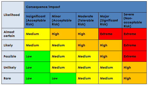
Risk Assessment and Management
One of the primary responsibilities of a safety officer on board is to conduct comprehensive risk assessments. This involves identifying potential hazards, evaluating their severity and likelihood, and implementing measures to mitigate or eliminate risks. Safety officers collaborate with other crew members, conducting regular inspections and audits to ensure compliance with safety protocols and regulations.
Safety Training and Education
Safety officers are responsible for organizing and delivering safety training programs for crew members. These programs cover topics such as personal safety, fire prevention, emergency response, and occupational health. By ensuring that crew members are well-trained and informed, safety officers contribute to the overall safety awareness and preparedness on board.
Incident Investigation and Reporting
When incidents occur, safety officers play a crucial role in investigating the root causes and contributing factors. They analyze incidents to identify trends, patterns, and systemic issues, allowing for targeted corrective actions. Safety officers also prepare detailed incident reports, which contribute to organizational learning and the prevention of future incidents.
Safety Equipment and Maintenance
Safety officers are responsible for ensuring that all safety equipment on board is in good working condition. This includes conducting regular inspections, maintenance, and testing of safety equipment, such as fire extinguishers, life-saving appliances, and communication devices. Safety officers also coordinate drills and exercises to test the effectiveness of safety systems and procedures.
Regulatory Compliance
Safety officers act as a liaison between the vessel and regulatory authorities. They monitor changes in safety regulations and ensure that the vessel remains in compliance. Safety officers assist in the preparation of safety management